Introduction Paragraph- Have you ever heard about Verilog Concatenation? What is the use of Verilog Concatenation? Where do we make use of it? How can we make use of it? Do you want to gain more knowledge about this concept? Then this is the page where you are going to find answers to all the questions popping up in your mind regarding Verilog Concatenation.
Answer Paragraph:- The Verilog Concatenation refers to the open and close brackets {,}. Concatenation in general terms is used to combine two or more vectors to form a resultant of a single vector. But on the contrary, in The Verilog, the Concatenation operator is used to either join two or more vectors or to break up two or more vectors into sub-smaller vectors.
Introduction to Verilog:-

Verilog is a word derived from a Latin word ” Veritas” carrying the meaning of “The Truth” and “Logos” meaning ” Idea or Reason”. So in simple terms, it can be stated that the word Verilog generally means- “Expressing the Truth of your Ideas”.
History of Verilog:-
Verilog Hardware Description Language ( HDL) was initially implemented and designed by Prabhu Goel along with Phil Moorby in the year 1984 at Gateway Design Automation. It came into usage at the beginning of the year 1985 and got extended substantially by 1987. In the initial stage, Verilog was a proprietary language which in simple words means that no one was allowed to make or design a simulator based on Verilog. But in December 1989, Cadence Design System took over Gateway and designed a simulator baSed on Verilog and continued to market both of them along. In December 1995, Verilog was registered under IEEE standard.
What is Verilog:-
Developed in 1984, Verilog is one of the many hardware description languages (HDL) developed and used in the hardware language industry. Verilog designs are made of many interconnected modules. It gives designers the chance to create designs at Register Transfer Level( RTL), Behavior Level, Switch Level, and even at Gate level also. Unlike C language it works in parallel and not in series combination. Surprisingly, Verilog is very efficient in defining everything right from a single bit to an entire computer system.
Verilog Framework:-
module module_name (x,y,z)
input x,y;
output z;
statements;
……………;
……………;
end module
Verilog Modelling Styles:-
- Gate Level Modelling:- It is low-level modeling and is also famous by the name of White Box Modelling. It is mostly used in designing combinational logic.
Gate level Module ( o, a, b )
input a,b;
output o;
and a1( o, a, b );
end module
- Data Flow Modelling:– This modeling is used to drive a value on the NET or the WIRE. On comparing it with Gate Level Modelling, this Data Flow Modelling has a higher level of abstraction. It is used at the time of designing combinational logic. It is also sometimes known as ” Black Box Modelling Style”.
Data flow Module (o, a, b )
input a,b;
output o;
assign o= a&b;
end module
- Behavioral Modelling Style:- This design is quite similar to that with C programs. It has a higher level of abstraction as compared to both the Gate level Modelling Style as well as Data Flow Modelling Style. Like Data Flow Modelling Style, this modeling style is also referred to by the name of Black Box Modelling Style.
module behave
reg a;
initial
a = 0;
always
#5 a = ~ a;
endmodule
Structure of Verilog:-
Verilog Object is generally divided into two parts:-
- Declaration- this is the one holding module list with IO list
- Implementation:- this is the one consisting of concurrent assignments and sequential assignments ( within the process) and also architecture with variable and signal declaration.
Verilog Value Set:–
- 0 is used to represent the false condition or low logic level
- X is used to represent the unknown logic level
- Z is used to represent high impedance logic level
- 1 on the other side is used to represent the true condition or high logic level
Properties of Using Verilog Hardware Description language:-
- It is highly independent of the use of technology
- It is very fast in its working procedure.
- Is also efficient in the performance of any parallel operations also
- Holds vendor neutrality
- Is highly reusable
- Also helps in reducing the design cycle
- Is highly flexible in design
- Gives one the ease of debugging
- Also shows flexibility in creating codes
Rules To Be kept in Minding Verilog Coding:-
- While performing modeling in combinational logic in the same always block, always make use of non-blocking assignments.
- While performing modeling in sequential logic, make use of the non-blocking assignments
- If you desire to or sometimes accidentally mix sequential and combinational logic within the same always block, then also make use of the non-blocking assignments.
- Never try to mix both blocking assignments and non-blocking assignments within the same always block.
- Verilog block statement is defined as many single concurrent or sequential statements imbibed between begin and end.
Verilog Operators:-
There are quite a great number of Verilog Operators of which few are depicted below:-
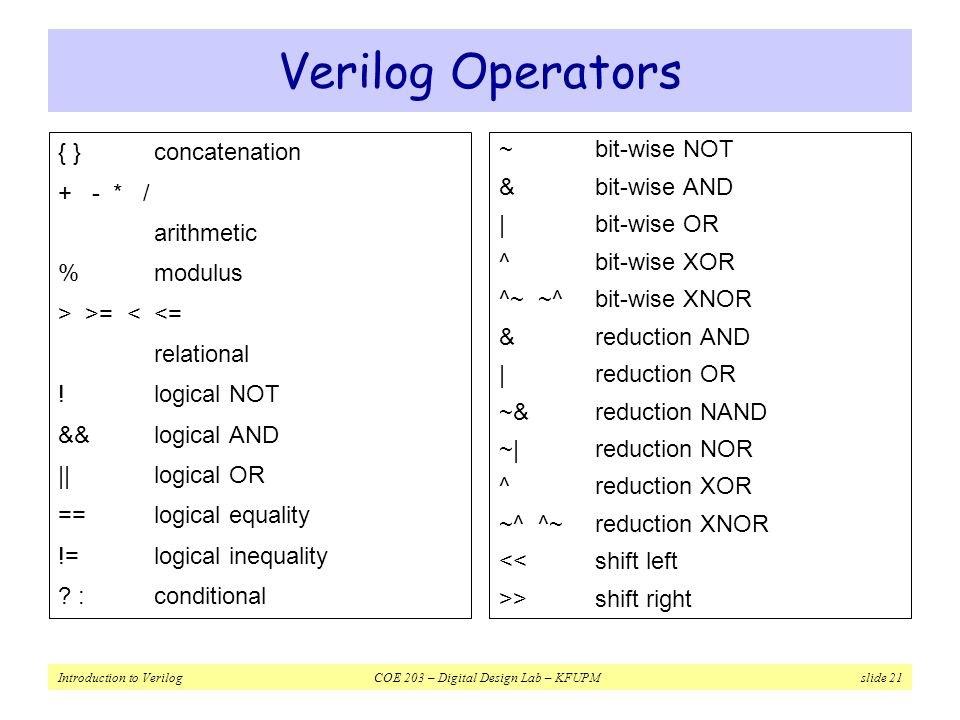
Concatenation Operator:-
- {op1, op2,——-} :- concatenation op1, op2 and so on to a single number
- Should have sized operands
reg a;
reg [2:0] b,c ;
. .
a = 1′ b 1;
b = 3′ b 010;
c = 3′ b 101;
catx = { a , b, c }; // catx= 1
_ 010_ 101
caty= { b, 2′ b11 , a } //caty=
010_11_1
catz= { b , 1 }. // WRONG !!
- Replication
catr = {4 {a} , b , 2 {c}}.
//catr= 1111_010_101101
Concatenation in Verilog:-
Verilog is one such that offers us several operators which can be used by us for performing a wide range of calculations and operations over our data. Making use of Verilog operators, one has to make use of logic circuits or boolean expressions that are required to be synthesized.
A concatenation operator is normally in use when there is a need of designing shift registers. It is not allowed to make use of unsized constant numbers in concatenation.
Illustration:-
1. To understand in a better way, let’s take an example, suppose we have single-bit signals that are 2 in number which we wish to combine to use as an address for the task called multiplexor.
Now to make use of the concatenation operator, we first have to make a list of the signals which we want to get combined within the area of curly brackets{}. Then we have to separate this list of signals by making use of a comma as shown {,}.
When we now make use of the Verilog concatenation operator, the bits placed in the output should match the order in which they are being listed inside the brackets {,}. The sequence of the bits has to be kept in mind otherwise the operator will not be functional at all.
For example, the code mentioned below would generate an output vector that displays the value 0011b.
1 | c ={ 2’b00, 2’11};
Verilog Concatenation Illustration:-
1|wire a,b; // 1-bit wire
2|wire [1 :0 ] res;. // 2-bit wire to store a and b
3|
4|// res[1 ] follows a, and res[0] follows b
5|assign res = {a,b}
6|
7|
8| wire [2:0] c;
9|wire [7:0]. res1;
10|
11| // res[0]. follows c[2]
12| // res[2:1] is always 0
13| // res[ 4:3] follows. c[1:0]
14| res[5] follows a
15| // res[6] follows b
16| assign res1 = {b, a, c[1:0], 2’b00 c[2]}
Conclusion:-
So Verilog is that hardware description language (HDL) which is used to club together multi-bit Verilog wires and Verilog variables to form a bigger web of multi net wire or variable with the help of concatenation operator ” { and }” generally separated by Comma. In addition to having variables and wires, Concatenation is also allowed to own sized constants and expressions.
Frequently Asked Questions:-
Q1. How can we design Verilog code to show the practical use of concatenation and replication?
Ans- Below given example is best to show the above
1| // Combine the signal a and b into a vector concatenation
2| c = {a, b}
3|
4| // Replicate Signal c 3 times
5| d = { 3{c} } ;
Q2. Is it possible to synthesize desired boolean expressions or logic circuits using Verilog?
Ans- Yes, one can synthesize desired boolean expressions or logic circuits using Verilog.
Q3. Is Verilog the same as the C language?
Ans- No, Verilog undoubtedly is somewhat similar to C language but working in Verilog one has to keep in mind the hardware language.
Q4.How can we perform basic arithmetic calculations in Verilog?
Ans- Basic Calculations on variables in Verilog can be performed easily using Verilog Arithmetic Operators.
Q5. Is the output of Verilog concatenation and Verilog Replication scalar or vector?
Ans- The outputs in both the Verilog concatenation and the Verilog Replication are vector types.
Q6. What can be said about the input type in Verilog concatenation and the Verilog Replication?
Ans- The inputs in both Verilog concatenation and the Verilog Replication can be either vector type or even single bit.
Q7. While using Verilog concatenation is it necessary that the output matches the order in which bits are placed inside the brackets?
Ans- Yes, indeed it is important otherwise the desired output can’t be obtained.